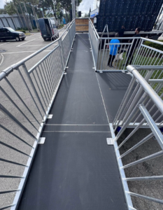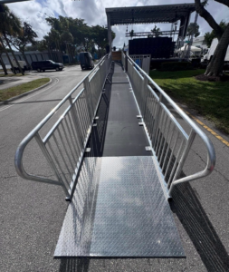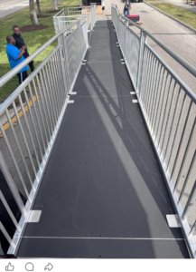
ADA HANDICAP RAMP, INSTRUCTION MANUAL & SETYP GUIDE.
ADA HANDICAP RAMP DRAWING
ASSEMBLY IN WORD
ADA HANDICAP RAMP NARRATED VIDEO INSTRUCTIONS
ADA HANDICAP RAMP BUILD GUIDE 5MIN
Step-by-step setup for the 48″ high wheelchair ramp in two layouts: Design A (L-shaped) and Design B (U-shaped). Page numbers refer to the combined ramp drawings (PDF).
Overview
Both designs take a wheelchair from the ground up to a 48″ high stage deck in two sloped runs, with a flat 24″ high landing halfway. The ramps are 4′ wide, built from Staging Dimensions SD5000 decks with black non-skid tops, and wrapped in a 42″ high aluminum picket guardrail.
| Design A — L-Shaped | Design B — U-Shaped | |
|---|---|---|
| Shape | Lower run, landing, then a 90° turn into the upper run | Lower run, landing, then a 180° turn back alongside the lower run |
| Landing | 8′ x 8′ at 24″ high (two 4×8 flat decks) | 8′ x 12′ at 24″ high (three 4×8 flat decks) |
| Lower run (ground to 24″) | 24′-4 7/16″ long | 24′-4 7/16″ long |
| Upper run (24″ to 48″) | 24′-9 5/8″ long | 24′-4 7/16″ long |
| Overall footprint | About 32′-4″ one way and 32′-10″ the other | 32′-4 3/8″ long x 12′-0″ wide |
| Top connection | Top adapter + 2 “C” clamps to the Apex stage | Top adapter + 2 “C” clamps to the Apex stage |
| Drawing pages in the combined PDF | Pages 10–14 (Layout “C”, Rev B), plus pages 1, 4–9 | Pages 20–21, plus lock details on pages 7–9 |
Each run climbs 24″ over roughly 24 feet, a slope of about 1:12. The same kit builds either design, but not both at once (the drawings say so). Design B also needs one extra 4×8 flat deck and one extra 8′ rail beyond the original kit.
The Apex stage the ramp connects to is not part of this equipment order.
Before you start
Build the stage first, then the ramp. This manual builds the ramp from the stage down, so every height is set off the fixed 48″ stage edge. The stage must be in place, level and locked before you set the first ramp piece.
Crew and tools
- At least 4 people. A 4×8 deck takes two people to carry and set.
- The T-handle wrench for the deck locks
- A 4′ level and a tape measure (25′ or longer)
- Chalk line or marking paint to lay out the footprint
- Gloves and safety-toe boots
- The printed drawings for the design you are building
Site prep
- Pick which side of the stage the ramp lands on and check there is clear, firm ground for the full footprint (see the Overview table). Leave about 5′ of clear, level space past the bottom of the starter ramp so a wheelchair can turn.
- Snap the outline on the ground: the 4′-wide ramp runs and the landing, measured from the stage edge.
- Check the ground for slope and soft spots. The legs adjust, but every leg foot needs solid bearing. On grass or soft ground, put plywood pads under the feet.
- Stage all parts along the layout in the order you will set them, with each leg set next to the deck it goes under.
Safety
- Never stand or walk on a deck until all its legs are in, it is locked to its neighbors and it is level.
- Install the guardrails before anyone uses the ramp, even for a test walk.
- Keep the ramp closed to the public until the final inspection checklist is complete.
Key to the drawings
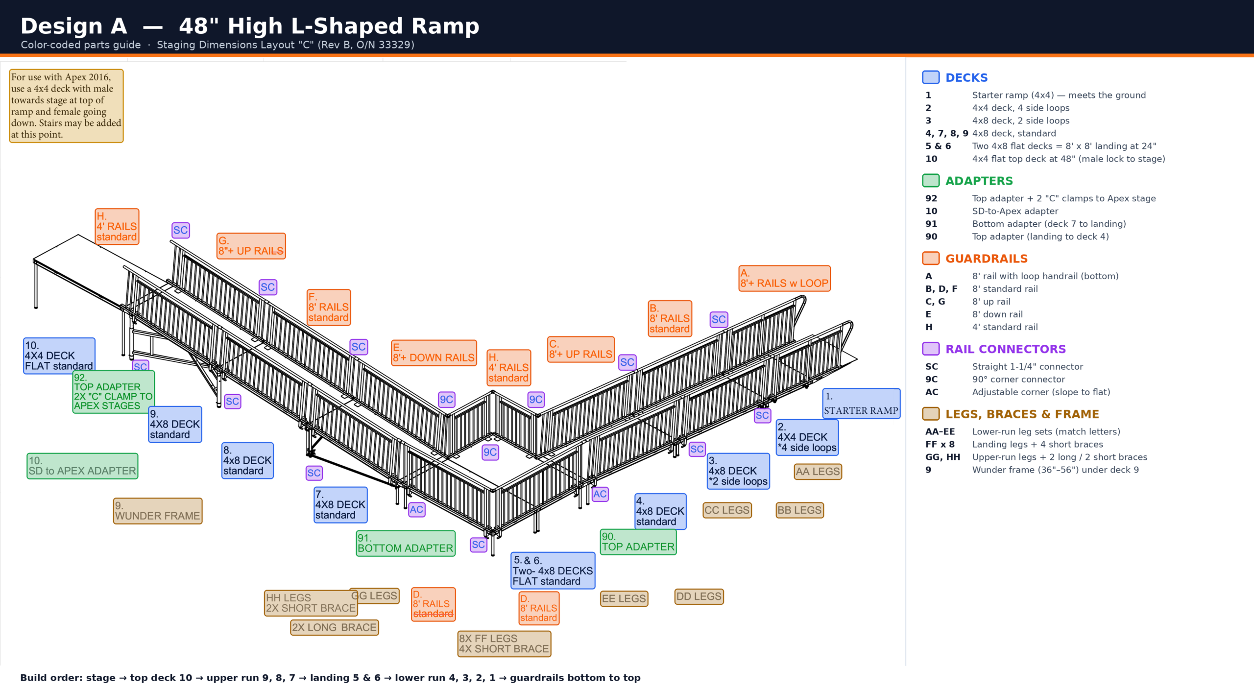
The layout drawings (pages 10 and 20) label every piece with a number, letter or code. Use this key to read them.
| Code on drawing | What it is |
|---|---|
| 1 / Starter ramp / Starter deck | SD5000 4′ x 4′ starter ramp — the sloped piece that meets the ground |
| Numbers 2–10 | Deck positions, counted from the bottom of the ramp to the top |
| “4 side loops” / “2 side loops” | Decks with side-mount guardrail receivers (the 4×4 with four, the 4×8 with two) |
| “Flat standard” | A deck set dead level (landing and top decks), not sloped |
| 90 / 91 / 92 | Transition adapter inserts (wedges) where a slope meets a flat deck |
| A | 8′ guardrail with the loop handrail end — at the bottom of the ramp, one each side |
| B, D, F, Extra | 8′ standard guardrail |
| C, G | 8′ “up” rail — extended guardrail (the kit’s “ext. top” / “ext. bottom” rails). Set it only where the drawing shows C or G |
| E | 8′ “down” rail — extended guardrail. Set it only where the drawing shows E |
| H | 4′ standard guardrail — short rails at the landing |
| SC | Straight 1-1/4″ guardrail connector — joins two rails in a straight line |
| 90C or 9C | 90° corner 1-1/4″ guardrail connector — square corners at the landing |
| ADJC or AC | Adjustable corner 1-1/4″ guardrail connector — where the rail bends from slope to flat |
| AA, BB, CC, DD, EE, FF, GG, HH legs | Leg sets, each cut to a different height. Match the letter on the leg to the letter at that spot on the drawing |
| Short brace / long brace | Leg braces that tie legs together |
| Wunder frame (wunderstructure) | 4′ x 8′ adjustable support frame, 36″–56″ high, used under the highest decks |
| M / F | Male / female deck lock positions (pages 13 and 5) |
On the diagonal-brace pages (6 and 14), each color is a different leg brace: orange X = 4′ x 8′ wunderstructure, red = 8′ long x 2′ high diagonal leg brace, magenta = 4′ long x 2′-4″ high diagonal leg brace, blue = 4′ long x 24″ high diagonal leg brace (straight ramp only).
How the deck locks work
Every deck edge that meets another deck has either a male lock (M) or a female lock (F), and an M edge always meets an F edge. Page 13 (L-shaped) shows where each M and F sits; check it before you set each deck so the edges face the right way.
The rule for both designs: the 4×4 deck at the top has its male side toward the stage and its female side facing down the ramp. Stairs can be added at that top 4×4 deck if needed.
To lock two decks together (page 7)
- Push the two decks tight together, edge to edge, with the male lock lined up on the female lock.
- Put the T-handle into the lock from the deck surface.
- Turn the T-handle to draw the decks together until it stops. The joint should be flush, with no step between decks.
Check the cam before you set a deck (page 8)
Look at the lock from the side. If the round edge of the cam is sticking out past the deck frame, the cam has to be reset or it won’t engage.
To reset the dual lock cam (page 9)
- Turn the T-handle counterclockwise until the cam hits the back of the lock.
- Keep turning counterclockwise one more full turn.
- The cam is now reset. Set the deck and lock it.
Design A — L-Shaped Ramp
Design A comes off the stage, runs about 24′-10″ down to an 8′ x 8′ landing at 24″, turns 90°, then runs about 24′-4″ down to the ground. Drawings: page 10 (layout and parts), page 12 (dimensions), page 13 (locks), page 14 (braces).
Pull list
| Position | Part | Qty |
|---|---|---|
| 10 | 4×4 deck, flat (top deck), plus the SD-to-Apex adapter | 1 |
| 92 | Top adapter with 2 “C” clamps to the Apex stage | 1 |
| 9, 8, 7 | 4×8 deck, standard (upper run) | 3 |
| 5 & 6 | 4×8 deck, flat (the landing) | 2 |
| 90, 91 | Transition adapters at the landing | 2 |
| 4 | 4×8 deck, standard | 1 |
| 3 | 4×8 deck with 2 side loops | 1 |
| 2 | 4×4 deck with 4 side loops | 1 |
| 1 | 4×4 starter ramp | 1 |
| — | Wunder frame (under deck 9) | 1 |
| — | Legs: HH and GG sets (upper run), FF x 8 (landing), EE, DD, CC, BB, AA sets (lower run) | as labeled |
| — | Braces: 2 long + 2 short (upper run), 4 short (landing), diagonal leg braces per page 14 | as shown |
| A | 8′ rail with loop handrail | 2 |
| B, D, F | 8′ standard rail | per drawing, both sides |
| C, G | 8′ up rail | per drawing, both sides |
| E | 8′ down rail | per drawing, both sides |
| H | 4′ standard rail | per drawing |
| SC, 9C, AC | Straight, 90° corner and adjustable corner connectors | per drawing |
Assembly steps
Stage 1 — Top deck at the stage (48″)
- Clamp the top adapter (92) to the Apex stage edge with its 2 “C” clamps.
- Set the 4×4 flat top deck (10) against the adapter, male lock toward the stage and female lock facing down the ramp. Use the SD-to-Apex adapter where the deck meets the stage.
- Set its legs, level it at 48″ so it is flush with the stage, and lock it.
Stage 2 — Upper run (48″ down to 24″)
- Stand the wunder frame where deck 9 goes, right below the top deck. Adjust it so deck 9 meets the top deck flush.
- Set 4×8 deck 9 on the wunder frame and lock it to the top deck.
- Set 4×8 deck 8, install the HH legs with the 2 short braces, and lock it to deck 9.
- Set 4×8 deck 7, install the GG legs with the 2 long braces, and lock it to deck 8. Deck 7 is the last sloped deck before the landing.
- Install the diagonal braces from page 14: a 4′ x 2′-4″ diagonal leg brace (magenta) across the ramp at the deck 8/deck 7 joint, and an 8′ x 2′ diagonal leg brace (red) along each side of deck 7.
- Check heights against page 12: about 3′-5/16″ and 2′-4 3/8″ from ground to deck at the two marked leg lines.
Stage 3 — Landing (24″)
- Set the two 4×8 flat decks (5 and 6) side by side to make the 8′ x 8′ landing, on the 8 FF legs with the 4 short braces.
- Level the landing at exactly 24″ in both directions.
- Fit the transition adapter (91) between deck 7 and the landing, and lock deck 7 to the landing.
Stage 4 — Lower run (24″ down to ground)
- Turn 90°. Fit the transition adapter (90) at the landing edge where the lower run starts.
- Set 4×8 deck 4 on the EE legs and lock it to the landing.
- Set 4×8 deck 3 (2 side loops) on the DD legs and lock it to deck 4.
- Set 4×4 deck 2 (4 side loops) on the CC and BB legs and lock it to deck 3.
- Set the starter ramp (1) on the AA legs and lock it to deck 2. Its front edge should sit flat on the ground with no lip.
- Check heights against page 12: about 12-9/32″ and 4-7/16″ from ground to deck at the two marked leg lines.
Stage 5 — Guardrails
- Start at the bottom. Mount rail A (8′ with loop handrail) on each side at the starter ramp and deck 2, using the side loops.
- Going up the lower run on each side: rail B (8′ standard), then rail C (8′ up rail), joined with SC straight connectors.
- At the landing: rails D (8′ standard) on the two outside edges and rails H (4′ standard) on the inside corner. Join the landing corners with 9C 90° connectors and the slope-to-landing bends with AC adjustable connectors.
- Going up the upper run on each side: rail E (8′ down rail) off the landing, then F (8′ standard), then G (8′ up rail), then H (4′ standard) at the top deck, joined with SC connectors.
- Tighten every connector and shake-test every rail.
Design B — U-Shaped Ramp
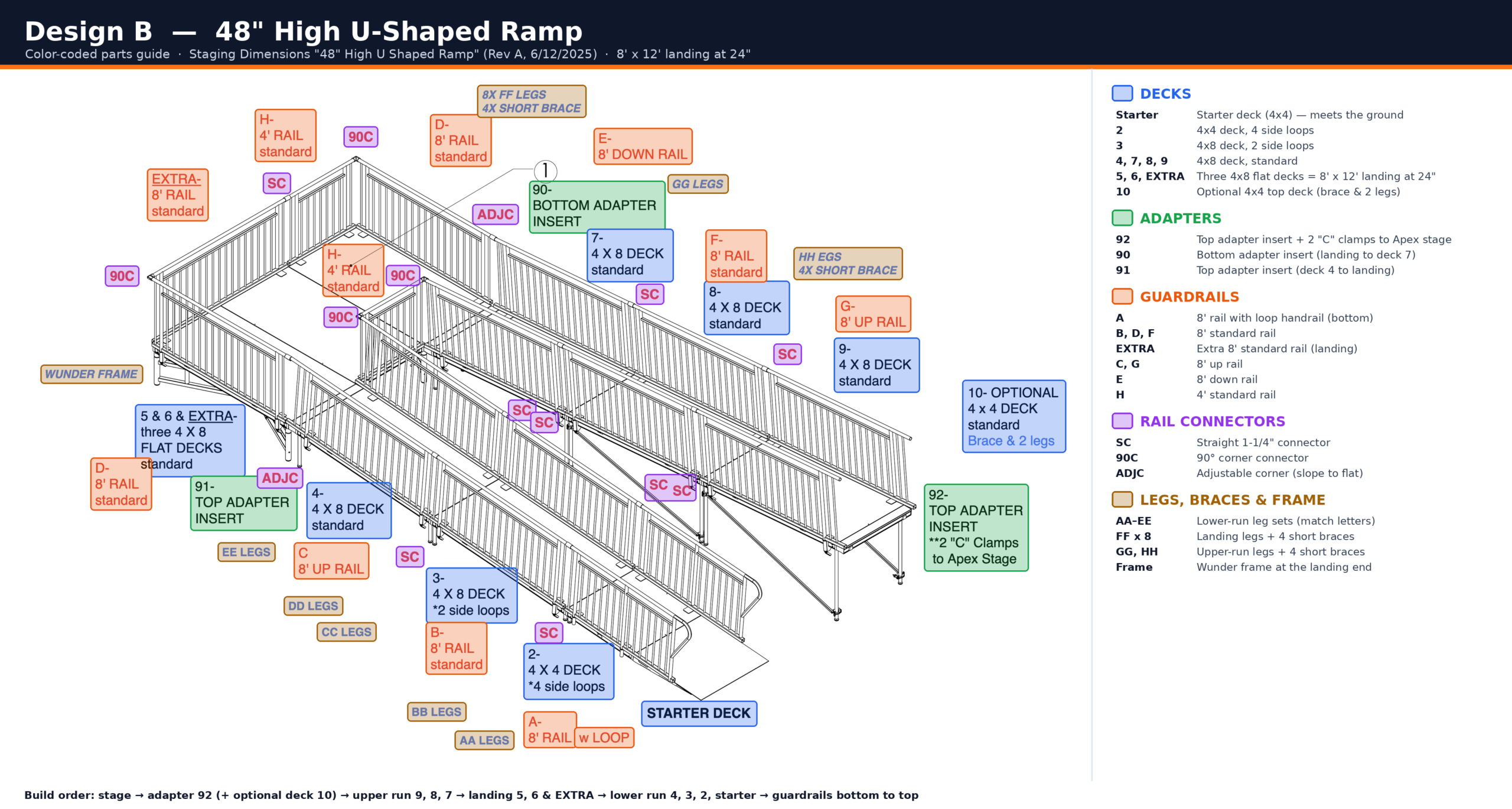
Design B comes off the stage, runs 24′-4 7/16″ down to an 8′ x 12′ landing at 24″, makes a 180° turn, then runs 24′-4 7/16″ back down to the ground, parallel to the upper run with a 4′ gap between them. The whole footprint is 32′-4 3/8″ long by 12′-0″ wide. Drawings: page 20 (layout and parts) and page 21 (dimensions). The U drawing set has no lock or brace sheet of its own, so use pages 7–9 for the locks and page 14 as the bracing guide.
Pull list
| Position | Part | Qty |
|---|---|---|
| 92 | Top adapter insert with 2 “C” clamps to the Apex stage | 1 |
| 10 (optional) | 4×4 deck, standard, with brace and 2 legs — adds a flat spot at the top | 1 |
| 9, 8, 7 | 4×8 deck, standard (upper run) | 3 |
| 5, 6 and Extra | 4×8 deck, flat (the 8′ x 12′ landing) | 3 |
| 90 | Bottom adapter insert (landing to upper run) | 1 |
| 91 | Top adapter insert (lower run to landing) | 1 |
| 4 | 4×8 deck, standard | 1 |
| 3 | 4×8 deck with 2 side loops | 1 |
| 2 | 4×4 deck with 4 side loops | 1 |
| — | Starter deck (4×4 starter ramp) | 1 |
| — | Wunder frame (shown at the landing end) | 1 |
| — | Legs: GG and HH sets (upper run), FF x 8 (landing), EE, DD, CC, BB, AA sets (lower run) | as labeled |
| — | Short braces: 4 at the landing, 4 at the upper run | 8 |
| A | 8′ rail with loop handrail | 2 |
| B, D, F, Extra | 8′ standard rail | per drawing, both sides |
| C, G | 8′ up rail | per drawing, both sides |
| E | 8′ down rail | per drawing, both sides |
| H | 4′ standard rail | per drawing |
| SC, 90C, ADJC | Straight, 90° corner and adjustable corner connectors | per drawing |
Assembly steps
Stage 1 — Top connection at the stage (48″)
- Clamp the top adapter insert (92) to the Apex stage edge with its 2 “C” clamps.
- If you are using the optional 4×4 deck (10), set it against the adapter now on its 2 legs and brace, level it flush with the stage at 48″, and lock it. Male lock toward the stage, female facing down the ramp.
Stage 2 — Upper run (48″ down to 24″)
- Set 4×8 deck 9 against the top adapter (or the 4×4 deck), set its legs and lock it.
- Set 4×8 deck 8 on the HH legs with 4 short braces and lock it to deck 9.
- Set 4×8 deck 7 on the GG legs and lock it to deck 8.
- Install the long diagonal leg braces under the upper run as shown in the side elevation on page 21, following the same pattern as page 14.
- Check the top end reads 4′-0″ from ground to deck.
Stage 3 — Landing (24″)
- Set the three 4×8 flat decks (5, 6 and Extra) to form the 8′ x 12′ landing, on the 8 FF legs with 4 short braces and the wunder frame shown at the landing end.
- Level the landing at exactly 2′-0″ (24″) in both directions.
- Fit the bottom adapter insert (90) between the landing and deck 7, and lock deck 7 to the landing.
Stage 4 — Lower run (24″ down to ground)
- Turn 180°. The lower run comes off the other half of the landing and runs back toward the stage side, with a 4′ gap from the upper run.
- Fit the top adapter insert (91) at the landing edge where the lower run starts.
- Set 4×8 deck 4 on the EE legs and lock it to the landing.
- Set 4×8 deck 3 (2 side loops) on the DD legs and lock it to deck 4.
- Set 4×4 deck 2 (4 side loops) on the CC and BB legs and lock it to deck 3.
- Set the starter deck on the AA legs and lock it to deck 2. Its front edge should sit flat on the ground with no lip.
Stage 5 — Guardrails
- Start at the bottom. Mount rail A (8′ with loop handrail) on each side of the starter deck and deck 2, using the side loops.
- Going up the lower run on each side: rail B (8′ standard), then rail C (8′ up rail), joined with SC straight connectors.
- Around the landing: rails D (8′ standard) and the Extra 8′ standard rail on the outside edges, and rails H (4′ standard) on the short inside edges at the ends of the runs. Join corners with 90C connectors and the slope-to-landing bends with ADJC adjustable connectors.
- Going up the upper run on each side: rail E (8′ down rail) off the landing, then F (8′ standard), then G (8′ up rail), joined with SC connectors.
- Rail both sides of both runs. The 4′ gap between the runs means each run needs its own inside rail.
- Tighten every connector and shake-test every rail.
Final inspection and teardown
Don’t open the ramp until every box below is checked.
Inspection checklist
- ☐ Top adapter is clamped to the stage with both “C” clamps, and the top deck is flush with the stage at 48″
- ☐ Landing is level at 24″ in both directions
- ☐ Every deck joint is locked, with no gap and no step between decks
- ☐ Starter ramp edge sits flat on the ground with no lip
- ☐ Every leg is on solid footing, and every brace and the wunder frame are in and tight
- ☐ Guardrails run the full length on both sides of every run and around the landing, with no open gaps
- ☐ Loop handrail ends (rail A) are at the bottom on both sides
- ☐ Every rail connector (SC, 90°, adjustable) is tight, and no rail moves when pushed hard
- ☐ Walk the whole ramp: no bounce, rock or loose deck anywhere
- ☐ Roll a wheelchair or hand truck up and down the full ramp as a final test
- ☐ Clear, level turning space at the bottom of the ramp
Teardown
Take the ramp down in reverse order: guardrails first, then decks from the bottom up, then the landing, then the upper run, and the top adapter last. Unlock each deck by turning the T-handle the opposite way. Before packing, reset any cam that is sticking out (page 9) so the decks are ready for the next build, and bag the connectors and clamps together.
Things to confirm before the event
The drawings leave five points open. Settle these with Staging Dimensions (sales@stagingdimensions.com) or on a test build before event day.
- ☐ Extra equipment for Design B. The U-shaped ramp needs a third 4×8 flat deck and an extra 8′ rail, both labeled “Extra” on page 20. The original kit (order 33329, page 1) has neither. Confirm they are on the truck.
- ☐ Wunder frame height under the U landing. Page 20 shows a wunder frame at the landing end, but the kit’s wunder frame adjusts from 36″ to 56″, and the landing is at 24″. Confirm which frame goes there.
- ☐ Adapter numbers are swapped between drawings. On the L (page 10), 90 is the top adapter and 91 the bottom adapter. On the U (page 20), 90 is the bottom adapter and 91 the top. Go by where the adapter sits, not its number.
- ☐ Leg letters. This manual places the leg sets from where their labels sit on pages 10 and 20. Check the letters stamped on the legs against the drawing arrows at each spot before setting decks.
- ☐ No brace sheet for Design B. The U set has no diagonal-brace page. This manual uses the L ramp’s brace layout (page 14) and the side elevation (page 21) as the guide. Confirm the brace layout with Staging Dimensions.
Source: Staging Dimensions drawings, “Equipment to Create 48″ High Ramp” (order 33329, Rev A/B, drawn 10/16/2024) and “48” High U Shaped Ramp” (Rev A, drawn 6/12/2025), combined in Handicap_Ramp_Drawings_Combined.pdf.